
www.magazine-industry-usa.com
04
'12
Written on Modified on
Eplan Fluid Professional: integrated engineering with mechanical system design
Solution provider Eplan presents enhanced fluid software that can now be integrated in the MCAD workflow. 3D data, fluid symbols and electrical actuation will be directly linked to the parts list and the technical specifications of the equipment in Eplan Fluid Professional. Users will benefit from interdisciplinary engineering and lower planning and documentation costs. The expertise of the fluid engineer in the overall project will increase at the same time.
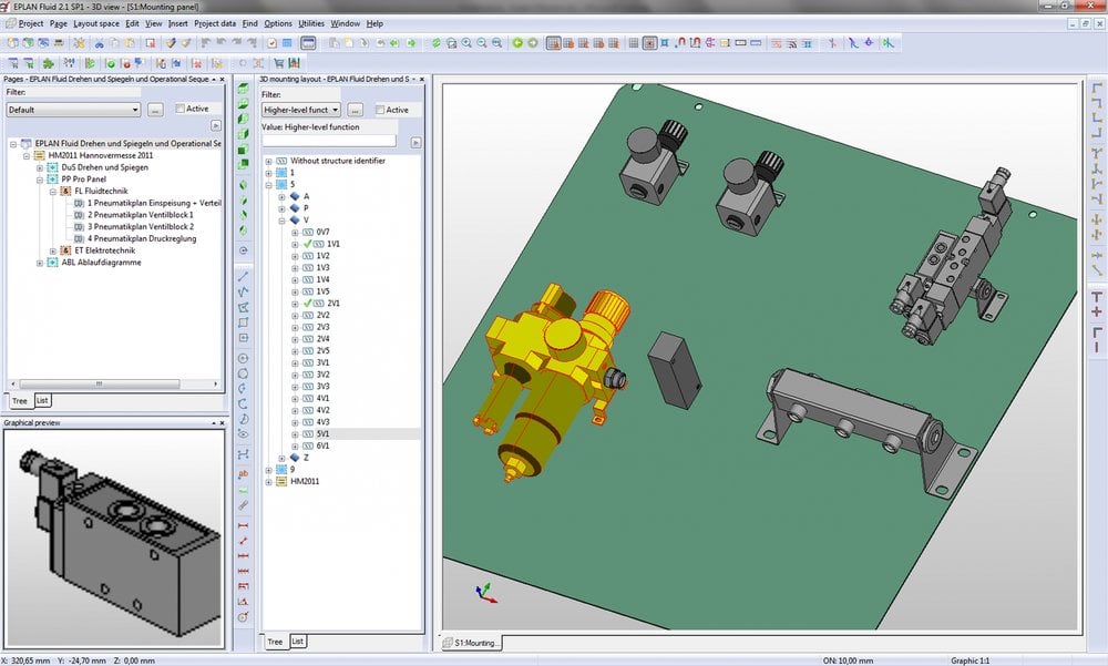
Eplan Fluid Professional combines tried and tested fluid system planning and new 3D technology. Components that have been placed in the fluid circuit diagram, such as valves or cylinders, can be assembled in 3D and put onto pasteboards using a simple method that is similar to the LEGO principle. The Eplan eTouch technology automatically generates pick-up points for each component and therefore makes it possible to set up fluid circuits quickly and easily. Users do not need in-depth 3D knowledge, and the 2D derivations and manufacturing drawings are created automatically as part of the documentation. Valuable manufacturing information is therefore available at an early stage such as the amount of installation space required, number of drill holes or hose lengths.
Controlled workflow using Step interface
One of the main new features is integration in the existing workflow of mechanical system design. Whereas the 3D model is designed in any MCAD system (Autodesk Inventor, for example), an installation space can be defined for the pneumatic components and their main compressed air supply and then exported to Eplan Fluid Professional using a Step interface. The fluid engineer then selects the components and the connections with direct links to the electrical engineering. Automatically generated parts lists and hose lists are available immediately. If the fluid engineer imports an installation plate, for example, they can position the planned components in the intended installation space in the circuit diagram using drag & drop and assemble it directly in 3D. The manufacturing information is created using dimensions, such as a pneumatic maintenance unit securing clamp. The fluid engineer then returns the result, including component numbering, to the MCAD model of the overall machine using the Step interface.
Standardization simplifies the process
Fluid engineers can standardize their engineering design using Eplan Fluid, and save and re-use frequently used subsystems in the form of macros directly in the designing. Specialist knowledge is therefore retained and can be retrieved at any time. This speeds up engineering and safeguards quality throughout all disciplines. Together with electrical engineering, the workflow also provides an opportunity to avoid costly errors, particularly in view of the increasing complexity of mechatronic components such as valve islands. The know-how of the fluid engineer is therefore used where it is needed: during the selection and dimensioning of components, the fluid system connections and their correct positioning. Aspects such as hose lengths, heat generation, energy efficiency, mechatronic interaction and reducing installation space can be calculated at an early stage in this multi-disciplinary workflow.
Summary:
The benefits for the engineer are obvious: 3D data, fluid symbols and electrical actuation are directly linked to the parts list and the technical specifications of the equipment. The result: engineering and documentation costs are reduced.
Images
fluid_EN.png: Simple 3D planning in Eplan Fluid Professional using eTouch technology.
