Achieving Interference-free Wireless Links by Keeping the Fresnel Zone Clear of Obstructions
By Henry Martel, Field Application Engineer, Antaira Technologies.

In the 1800s, French physicist Augustin-Jean Fresneluncovered a phenomenon now known as the Fresnel Zone. Although Fresnel certainly didn't know it then, his discovery would have profound impact on modern wireless communications.
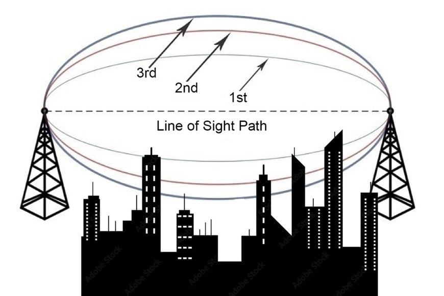
The Fresnel Zone is the elliptical-shaped 3D region around a transmitted radio beam’s path between its wireless transmitter and receiver. Thinnest at the endpoints and widest in the center, the radius of the Fresnel Zone determines the clearance needed between antennas to ensure that the transmitted signal is received with minimal interference. Obstacles in the path of the Fresnel Zone will cause radio waves to go out of phase and interfere with one another, especially when they are at similar frequencies. Retransmissions, decreased data speeds, packet loss, and poor signal quality can all result from signal obstruction.
To learn how to overcome these issues or better yet avoid them all together, let's take a trip into the Fresnel Zone.

The Problem of Out-of-Phase Signals
Achieving visual Line of Sight (LOS) between the radio transmitter device and receiver is the first rule to follow while configuring a wireless link, whether it is point-to-point or multi-point. Visual LOS is defined as the ability to “see” the receiver, transmit antenna or other device (i.e., receiver or antenna) fully, clearly, and unhindered from either position. However, an unobstructed visual LOS is not enough to establish high signal quality.
Here’s why: Whenever a radio wave is propagated from a transmitter, the path of it spreads out the farther it gets from its source. Ideally, that signal will continue traveling until the point where it dissipates. In the real world, of course, that is not likely. Radio signals are far more apt to encounter an obstacle in their path, be it a building, a body of water, a tree, or a concrete wall, that will reflect it back in the direction of the receiver. Because the path of the signal is now traveling a further distance, it will be knocked out-of-phase with the strongest signal from the receiver by the direct path wave, and it will reduce the received signal strength.
This unwanted event is known as “phase cancelling”. Its magnitude and frequency is a function of wireless signal strength operating frequency, distance and how out-of-phase the receiver deflected signal is with reflected wave, typically described in terms of an angle (0-360°). A difference of 180° means the receiver and waves are completely out of phase, while a phase difference of 360° occurs when the receiver waveforms are perfectly aligned.
To maximize signal strength at your receiver, you must minimize interference from out-of-phase signals. So, in addition to visual LOS zones, wireless internet links and devices require radio frequency LOS zones or “RF LOS zones,” which refers to a clear Fresnel zone between light waves and the antennas and devices.
Planning for Fresnel Zones
The Fresnel Zone consists of multiple zones. The first three zones are the most important. Zone 1 has the strongest signal strength, Zone 2 is weaker, and Zone 3 is weaker still.
Being the innermost region, the first Fresnel zone line (Zone line 1) is also the area most important. Zone line 1 is the location where the signal is strongest and therefore most likely to be impacted by obstructions. Another reason for concentrating on Zone line 1 is that its contributions are positive to phase shift, whereas obstructions in Zone line 2 are negative and may actually strengthen the signal.
Like all Fresnel zones, Zone 1 expands left and right as well as up and down the axis so it has to be analyzed in three dimensions for obstructions. To maintain a good connection, the general rule of thumb is that Zone 1 must be 60% clear of obstructions from the distance of the center line of sight or straight line to the Zone’s outer boundary line. Beyond 40%, signal loss will become significant at higher frequencies. For optimum performance you should aim for zones with no more than 20% obstructed, the less the better.
Overcoming Fresnel Zone Obstacles
Calculating the radius of Zone 1 is critical for your wireless link as it will enable you to decide if an obstacle within the Zone one radius will or will not have a significant impact on signal strength. Keep in mind that an obstacle can be stationary or moving; for instance, buses, trains, cars, buildings or even pedestrians cause temporary losses of function of strongest satellite signal.
There are numerous online calculators for determining Zone 1 radius. Basic calculators will ask only for frequency and then calculate the distance between the antennas. More sophisticated calculators will let you calculate and enter the distance of the obstacle from the line-of-sight antennas, along with its height to determine if it falls in the Fresnel Zone radius. Some calculators even factor in the curvature of the earth since the ground becomes an obstacle in longer distance for satellite links.
In the event you identify obstacles in the primary Fresnel Zone, you can pursue a few alternatives for the primary Fresnel Zone resolution. For one, elevate the antennas to effectively raise the Fresnel Zone clearance. Two, change the path and direction of the link by moving the position of an antenna. Another solution, if possible, is removing the obstacle from the path of the LOS and the area around it.
Still another workaround would be reducing space for the Fresnel Zone. Its radius and size depend on the frequency of the signal the higher the frequency, the smaller the radius of the space for the Fresnel Zone. In addition, as the distance between antennas is reduced, the Fresnel Zone radius, space and size will decrease. Directional antennas featuring narrow beam widths will also reduce the radius and space for a Fresnel Zone.
Building a successful long-lasting wireless solution requires taking into account any potential deterrence to that performance, including the Fresnel Zone. In industrial settings or crowded urban areas, overcoming obstacles in a Fresnel Zone can be difficult but rarely impossible with the right equipment, wireless solutions, and proper guidance.
www.antaira.com

